Part 1: Overlay Networks in Data Centres
Overlay technologies for providing network virtualization have a long history in the industry. A current incarnation can be seen in more or less every Service Provider network these days that run MPLS-based services like L2VPNs, L3VPNs or EVPNs.
Network operators were keen to adopt these technologies in their networks as they provide a flexible way of introducing new features and customers to an existing network. At the same time these networks scale in a very reliable way, by differentiating the role of the equipment according to its function. An example of this is that we have MPLS edge routers (PE or LER) that have detailed knowledge about the customer networks that they need to serve and then MPLS core routers (P or LSR) that don’t have any state about customer networks, but provide pure connectivity between edge routers. Essentially this means that there is no single edge router in the network that has to know the states of all customers, but just the ones it needs to serve. Core routers are just aware about the carrier’s own network and can be optimized to provide fast processing of transit traffic while edge routers provide lower density, but more features.
As MPLS networks got more and more common, there were also approaches to stretch the MPLS domain from the WAN to the datacenter up to the Top-of-Rack (ToR) Switch in order to address scalability issues seen with traditional Layer 2 based Datacenters. Essentially this would have meant that each ToR Switch would act as a PE router in the MPLS network. There was only little adoption to this principle, as this increased the complexity of ToR switches and still did not solve the integration problem between the computing layer and the network layer. There was still a need to run VLANs between the Switch and the hypervisor in order to attach virtual machines to the correct network.
With the ascent of Software Defined Networking (SDN) new efforts were made to bring overlay networks to data centers, however this time the edge function was moved moved down to the hypervisor on the computing layer. Additionally, a new set of overlay technologies besides MPLS became popular, of which one is VXLAN.

Moving the edge function down to the computing layer was a natural choice, because this device knows exactly which virtual machine (VM) belongs to which virtual network (VN). ToR switches in these scenario are somewhat degraded to provide IP connectivity between different hypervisor nodes. Although the technology used might be different, the concept is still the same and provides the same benefits as in MPLS-based networks. The number of forwarding entries on the ToR switch – regardless whether these are Layer 2 or Layer 3 – is only depending on the number of hypervisors, but not on the number of virtual machines as before.
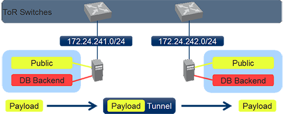
The life on a packet that is sent from one virtual machine on one hypervisor to another VM in the same virtual network that is located on another hypervisor is very similar to the life of a packet sent by a customer towards an MPLS enabled PE router:
- The packet is received on the hypervisor on a virtual ingress port.
- The hypervisor knows to which virtual network this port belongs and can make a lookup (could be Layer 2 if the destination is in the same virtual network, or Layer 3) based on that information.
- When the lookup has been performed the original packet get’s encapsulated with a new header and the destination IP address of the new header is the destination hypervisor.
- The packet is handed off to the physical network. The physical network makes the forwarding decision only based on the outer IP header and does not look into the packet payload.
- Eventually when the packet is received on the egress hypervisor, it gets decapsulated and forwarded to the correct virtual machine.
The egress hypervisor uses information from the overlay header in order to determine the correct virtual network that this packet belongs to. While the mapping between a packet and a routing context (VRF in MPLS terms) was done with a label in MPLS networks, VXLAN uses the Virtual Network Identifier (VNI) that is part of the VXLAN header.
The fact that only IP connectivity is required for running these kinds of network enables data center operators to use pure IP Fabrics in their data center and still provide Layer 2 connectivity across the data center on the overlay if needed. Besides IP connectivity also support for jumbo frames is highly recommended in these implementations in order to prevent massive packet fragmentation that could occur because of the added overlay header.
Continue with Part 2: Using hardware VTEPS to integrate physical devices
Share your opinion with us!
Your perspective counts! Leave a comment on our blog article and let us know what you think.
.png?width=300&height=300&name=Design%20ohne%20Titel%20(7).png)
